
Product Description
Servo, under contract to NASA, Goddard Space
Flight Center has developed a 120 x 5 degree instantaneous
field-of-view (FOV) Wide Angle Earth Sensor (WAES) for use on
missions that require a "safe hold" with some level of
pointing accuracy to protect payloads from viewing the Earth.
Developed especially for NASA’s WIRE (Wide-Field Infrared
Explorer) mission, the WAES consists of two Sensor Heads and an
Electronics Control Unit. On the WIRE mission the sensor heads 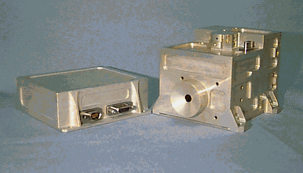 are arranged back to back 180 degrees apart
such that they can monitor one axis of rotation, while a sun
sensor is used for the other axis. The predicted accuracy is 1.5
degrees exclusive of radiance errors and 3.5 degrees inclusive of
radiance errors.
are arranged back to back 180 degrees apart
such that they can monitor one axis of rotation, while a sun
sensor is used for the other axis. The predicted accuracy is 1.5
degrees exclusive of radiance errors and 3.5 degrees inclusive of
radiance errors.
Design Approach
The design criteria for the Wide Angle Earth Sensor were to keep it small, light and inexpensive. The WAES consists of two Sensor Heads and an Electronic Control Unit (ECU). The ECU is the interface to the spacecraft and also connects to the two Sensor Heads. The ECU contains a DC-DC converter and some electronics to buffer and subtract the signals from the Sensor Heads.
The Sensor Heads contain the detector, optics, signal processing electronics, resonant chopper and chopper driver electronics. The detector uses a pyroelectric element that has one long pixel used for position information and a small pixel used for radiance compensation. Since the detector is pyroelectric and the Sensor Head operates in a staring mode, it is necessary to have an integral chopper. In this case the chopper is designed to be mechanically resonant at about 10 Hz. That it is mechanically resonant minimizes the power needed to operate it. The chopper itself consists of a mass fixed to a flex pivot. The flex pivot provides frictionless rotation for the chopper. The drive electronics consist of a drive coil and a pickup coil for feedback. The circuitry provides a little push on each swing to overcome any loses.
The optics were kept simple, a single element in an anastigmatic arrangement, reminiscent of the early box cameras. We did make use of diamond turned aspheric figures on both surfaces to control aberrations, primarily spherical. Stop position was used to control coma and astigmatism. An added benefit of the stop up front is that it reduces the field angle in image space. This is important in a wide-angle system, as light fall-of goes as the fourth power of the cosine of the field angle in image space.
The signal processing consists of taking the signals from the detector and amplifying them and synchronously demodulating them. After demodulation the signals are fed through a low pass filter to yield DC signal levels. An additional signal is generated from an on board temperature transducer. These signals then feed into a multiplier to yield an output that is proportional to the amount of Earth within the field of view. This output is then corrected for the light fall-off in the optics. This is done be switching in different gains depending on the signal level. The effect is to straighten out the "S" shaped signal versus position curve that would normally result as the Sensor Head is scanned across the horizon.
Construction
The construction is relatively straightforward. The ECU has been compartmentalized to separate the DC-DC converter from the rest of the electronics. This is necessary to keep the electrical noise generated by the converter from getting into the rest of the electronics.
The Sensor Heads are machined so that one piece forms 4 sides of the enclosure and the cover forms the other two. The components consisting of the mechanical parts and 3 printed circuit boards are packed in with little room to spare. The entire system of two Sensor heads and the ECU weighs approximately 2 1/4 pounds.
Theory of Operation
The WAES is required to output a signal that increases as the spacecraft rolls and more of the Earth enters the field of view. The instantaneous field of view needed to be at least 100 degrees and the cross direction should not be more than 10 degrees.
A single long pixel is situated to view the Earth’s horizon as well as a section of Earth and Space. As the spacecraft rolls the signal out of this pixel changes, increasing as more Space is viewed. With the spacecraft not experiencing any roll the signal out of the pixel can still change. This change can be caused by two factors; one is that the section of Earth within the FOV changes in temperature, and the other is that the detector’s temperature changes.
The pyroelectric detector produces a signal that is a function of the radiant power difference between itself and the scene it views. This difference will change if either the scene changes in temperature, or the detector changes. To correct for changes in the Earth’s temperature a second pixel is added to view just the Earth. This second pixel implements a radiance correction scheme. To correct for changes in the detector’s temperature, a temperature transducer is incorporated into the circuitry to correct for ambient temperature variations. The gains for the two pixels are set that their outputs are equal when viewing the same scene. The temperature transducer is set up to generate a signal that is equal to what the pixels would output if they were viewing strictly Space. We then have three signals, the temperature transducer signal which we will call SPACE, the small pixel viewing the Earth which we will call EARTH, and the large pixel which normally would be viewing a combination of Earth and Space, which we will call SIGNAL. The position is then given by the following equation:
Position = (SPACE - SIGNAL) * Scale Factor (1)
SPACE - EARTH
The scale factor can be ignored for the time being it is just used to set the range of the Position output. The value SIGNAL can range between SPACE and EARTH. This means that Position would range between 0 and 1.
SPACE ³ SIGNAL ³ EARTH (2)
0 £ Position £ 1 (3)
What equation (1) is performing, is a linear interpolation and normalization of the SIGNAL output. If the spacecraft rolls far enough the small pixel would end up viewing Space and the equation’s denominator would go to zero. Out of range logic has been implemented to deal with such a situation. The accuracy requirement of the system has to be better than 5 degrees over the field of view. The predicted accuracy is 1.5 degrees exclusive of radiance errors and 3.5 degrees inclusive of radiance errors.
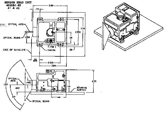
WAES Specifications
Sensor Head: 0.425
Electronics: 0.185
Head: 6.5 x 8.4 x 9.7
ECU: 8.3 x 10.6 x 2.8
Outline
For further information on Servo's products please call 516
938 9700 ext 352 or email ![]() us.
us.
